Magnetic Loop Antennas – brief theory and a practical design for 3.5 – 14 MHz

Magnetic Loop Antennas – a brief theory and a practical antenna for 3.5 to 14MHz

ABSTRACTS u2013 2017 | 2018 by Marica Martella is licensed under CC-BY-NC-ND 4.0

For Radio Amateurs wishing to use HF bands below 30MHz, the physical size and height above ground of conventional antennas can be a problem. They require towers or at least a support to allow the antenna to be a substantial fraction of a wavelength above ground. For the lower frequencies this is impractical for most domestic installations. An unbalanced antenna such as a vertical or long wire fed against ground will require a low resistance earth or radial system which may present its own problems. Even an extensive radial system may have significant earth resistance (20-30 ohms). If the antenna is much less than a quarter wavelength in height it will have low radiation resistance in the order of a few ohms and reduced efficiency when fed against a lossy ground. A balanced antenna such as a dipole or beam will not perform well if it is much less than a wavelength above ground due to a high angle of radiation.

Some locations will not allow antennas at all due to council or strata regulations or neighbour objections.

Magnetic loop antennas have become popular in recent years as they solve many of these problems. They have long been used in military or shipboard applications where space is at a premium or where the antenna must be discreet. They can be used as a “stealth” antenna and hidden in a roof space for example.

They are physically small, balanced and can perform well at relatively low heights above ground.

But of course as the old adage says – “you dont get something for nothing”.

In this case bandwidth and radiation resistance are sacrificed for small physical size.

Loop antennas must be carefully designed but their performance can rival conventional full size antennas.

Apart from small physical size and good performance at low heights they have the advantage of good noise immunity and are directional to some extent.

Theory

Magnetic vs electrostatic fields

Conventional antennas respond essentially to electrostatic fields. On the other hand a “magnetic loop” antenna responds to the magnetic field and the flux through the loop – it can be thought of as a 1 turn secondary of a transformer, with the primary being the radiation source for the received signal. Indeed a magnetic loop may be completely shielded with a grounded electrostatic shield and it will still function. This property makes it less sensitive to electrostatic noise sources such as nearby electronic equipment, motors and power lines. The Loop equivalent circuit is shown in Fig 1.

Equivalent circuit (Fig 1)

The loop acts as a lumped inductance – in most designs this is tuned with a capacitor to resonate the loop on a particular frequency. Inductance is proportional to loop area, which in turn is determined by circumference (assuming a circular loop) or the length of the loop conductor for other shapes. There is also an equivalent series resistance which is comprised of ohmic losses in the loop components and radiation resistance. Radiation resistance is low for loops which are a fraction of a wavelength at the frequency of operation – typical values are in the order of 0.1 Ohm. Ohmic losses in joints and the connection between the capacitor rotor plates and terminal should be small but should be considered due to the high RF currents involved. If high quality materials such as heavy copper tubing and silver soldered joints are used in the loop construction, ohmic losses can be minimized.

Due to the low equivalent resistance in the circuit, the loop acts as a very high Q tuned circuit. This may be an advantage for fixed frequency operation as it will attenuate unwanted strong signals off frequency. At low frequencies the 2:1 SWR bandwidth may only be a few KHz. However if the loop is to be tuned this imposes design challenges as the tuning is very critical.

A typical loop can be tuned over a 2 octave (4:1) frequency range. The loop shown in this article will tune from 3.3 to 14.8MHz with a variable capacitor of approximately 20-350 pF

RF Current and Voltage

RF Current is high in the loop due to the low radiation resistance. It may be up to 100A with a 1KW input to the antenna. Thus ohmic losses are important for higher power use and for efficiency. There is a well known “RF Skin effect” in conductors – the best results are obtained with a wide diameter conductor such as the 20 mm copper pipe used in this project.

To minimize ohmic losses use a single smooth piece of copper and silver solder joints where possible rather than screw or press connections. For practical purposes, the RF current is constant around the loop.

On the other hand, RF voltage is maximum at the tuning capacitor and minimum (approaching zero) opposite the capacitor as the loop is balanced. For high power the RF voltage across the tuning capacitor is substantial and may be as high as 10KV peak to peak for a 1 KW power input. For high power transmitting, a capacitor with wide plate spacing must be used. The ideal is a vacuum variable capacitor with an appropriate voltage rating

Matching the loop

Clearly no antenna is useful unless it can be attached to a feedline. Various matching schemes have been devised. (ref 1)

Gamma match

Because voltage varies around the loop and current is relatively constant, the impedance varies around the loop. Both balanced and unbalanced schemes have been proposed to connect the feedline to a point in the loop where there is a best match . In theory a balanced feed would give better noise immunity, but in practice this seems difficult to quantify.
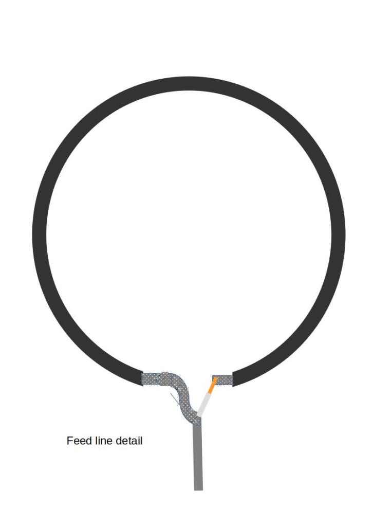
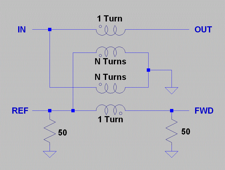
Loop match (Fig 3)

This appears to be the simplest in practice and most widely used. The impedance transformation is proportional to inverse of magnetic flux through the two loops which in turn is proportional to the ratio of the loop areas. The Impedance transformation ratio appears experimentally to be roughly the inverse of the ratio of the two loop areas squared. I used a 1m length of RG6/U 75 Ohm coax for the matching loop. This is cheap, insulated and fairly rigid. In this application it is simply a length of conductor. I joined shield and centre conductor together at both ends.

The feedline centre conductor connects to one end while the feedline shield connects to the other. In my case I used RG58/U as the feedline.

While the matching loop area affected the match, various other factors dominated.

I spent some time experimenting with various size loops.

The distance of the main loop conductor from matching loop was important – best results were obtained with the matching loop applied against the main loop. Height above ground and proximity to other metal objects affected the match as is the case with other antennas.

The loop and matching loop must be in the same plane – indeed one author (ref) tuned the match by rotating the plane of the matching loop.

Matching is relatively constant over several octaves of bandwidth. By adjusting loop area a good match can be obtained at least in middle of the operating range. In my case I obtained a near perfect match on 14MHz but a less than perfect match on other frequencies with the SWR as high as 1.7 on 3.5MHz

It will be necessary to finalize matching by trial and error

A Practical Magnetic Loop antenna for 3.5 to 14MHz

The Loop

I used 20mm copper tubing in this antenna with a length of approximately 4.9m. This length can be changed to achieve the desired range of frequencies. Be careful to use soft copper tubing – hard annealed copper will be difficult to bend. I did not take any particular care to get a perfectly round loop but a pipe bender could be used to do so. Copper tubing is available from hardware or plumbing suppliers.

Use a continuous length – any joints will have ohmic losses and any discontinuities will increase losses due to the “skin effect” at RF. I used 40mm plastic plumbing pipe as a support for the loop – it may be necessary to use something (nonmetallic) more substantial for high wind situations. A hole is drilled at the top for the copper and matching loop and I used a plastic cap on the pipe to prevent water ingress. I soldered heavy silvered copper wire to the ends of the loop for attachment to the tuning capacitor via terminals which were crimped and soldered. The ends of the loop are then covered with heavy heatshrink and fixed to the capacitor box with brackets and U Bolts. (see photo)

Tuning Capacitor

A local amateur (Greg VK8MD) kindly donated a surplus high power 20-350pF tuning capacitor. The voltage rating of the tuning capacitor is important in this application.

This capacitor has a plate spacing of 1.2mm. In air the breakdown voltage rating is approx 3KV/mm.

This should be adequate for power to 100W or so though I have only tested the system with 5W so far. Various authors recommend vacuum capacitors in this application. These are generally “multiturn” for an automatic vernier effect, low loss and high voltage. But they are fragile and expensive – it was going to cost AU$1000 to land a single capacitor in Australia from one US supplier. I did source some massive high voltage Russian devices for a reasonable cost from Poland – I will investigate using these in a future project

Motor Drive for tuning

A Polulu Stepper Motor ( Unipolar/Bipolar, 200 Steps/Rev, 42×48mm (NEMA17) , 4V, 1.2 A/Phase – Polulu #1200) was used to drive the capacitor. The capacitor traverses its adjustment range in half a turn and can be rotated continuously. Capacitors that have a “hard” endstop such as a some “broadcast” types or a vacuum capacitor may have to have some sort of sensing so that the motor does not drive past the endstop and damage the capacitor – these stepper motors have quite a lot of torque. While it is possible to detect a motor “stall” this does not seem to be very reliable. For a multiturn capacitor some sort of linear actuator would have to be devised – I have not investigated this. Another possibility is to limit the motor drive current – this can be set in software. In this application motor speed is not an issue.

Using a motor driver board, this motor can be configured in “microstep” mode. The motor has 200 steps per revolution and the microstep option allows 32 “microsteps” per step of the motor. Thus 3200 steps are available over the range of the loop (1/2 X 200 X 32) – this is sufficient for tuning even though the loop is very “sharp”. The motor is mounted in a plastic box using Polulu hardware.

Insulated Coupling

The motor and associated circuitry must be insulated from the Loop and tuning capacitor because of the high RF voltages involved. I used a surplus plastic kitchen cutting board to make an insulated coupling, but there are no doubt other options. Three circular pieces of 40mm diameter were cut from the board using a hole saw.

Two metal couplings (Pololu Universal Aluminum Mounting Hub for 5mm Shaft, M3 Holes (2-Pack) #1998) were bolted to the plastic discs with the third disc acting as an insulator between them. Using M3 hardware the components were assembled and the shafts of the motor and tuning capacitor fixed using grubscrews. The motor shaft has a “flat” to allow firm fixation. A small depression was drilled in the shaft of the tuning capacitor to allow the grubscrew firm purchase (Fig). The diameter of the tuning capacitor shaft was such that the hole in the metal coupling had to widened slightly using a drill.

Control Logic

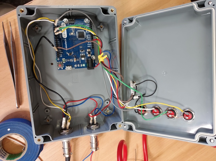
An Arduino Leonardo board was available from a previous project

The motor itself was driven by a second board (Polulu Tic T825 #3130) which allows proper sequencing of the coils in the stepper motor, has a rich instruction set, a motor driver and a interface circuitry which allows the board to be driven by various logic protocols including USB, I2C, TTL and serial

I used this as the first prototype for the motor control. A Polulu Stepper Motor Library is available for Arduino which simplified coding considerably. I set up push buttons for large steps and fine tuning up and down. I used the NanoVNA to find the current resonance of the loop and tune it.

The tuner requires 9-12V at 1.5A max – supply voltage and control signals are sent to the antenna via a multicore cable designed for garden irrigation controller use.

The Arduino software sketch is listed in the appendix

I am using the Tic T825 stepper control board in serial mode. The Motor serial device number must be set to its default value of 14. The Control board is an Arduino Leonardo with 4 pushbuttons normally open on lines 2,3,4,5

The Tic’s control mode must be set to “Serial/I2C/USB”. The baud rate should be set to 9600 and CRC should not be enabled. This example uses the compact protocol, so the Tic’s device number is not used, and can be set to anything.

Several libraries are included

#include <Tic.h>

at https://github.com/pololu/tic-arduino

#include <Pushbutton.h>

https://github.com/pololu/pushbutton-arduino

Originally I intended to calibrate the system so it could jump to a known position in terms of microsteps. This would allow the loop to be set to a known frequency. However I found that there was “slippage” in position and some backlash in the tuning mechanism. There is lots of scope for improvement of this system. Using the NanoVNA for tuning is somewhat slow and tedious for routine use – at some point I will develop an automatic antenna tuner – this is one of many projects for later!

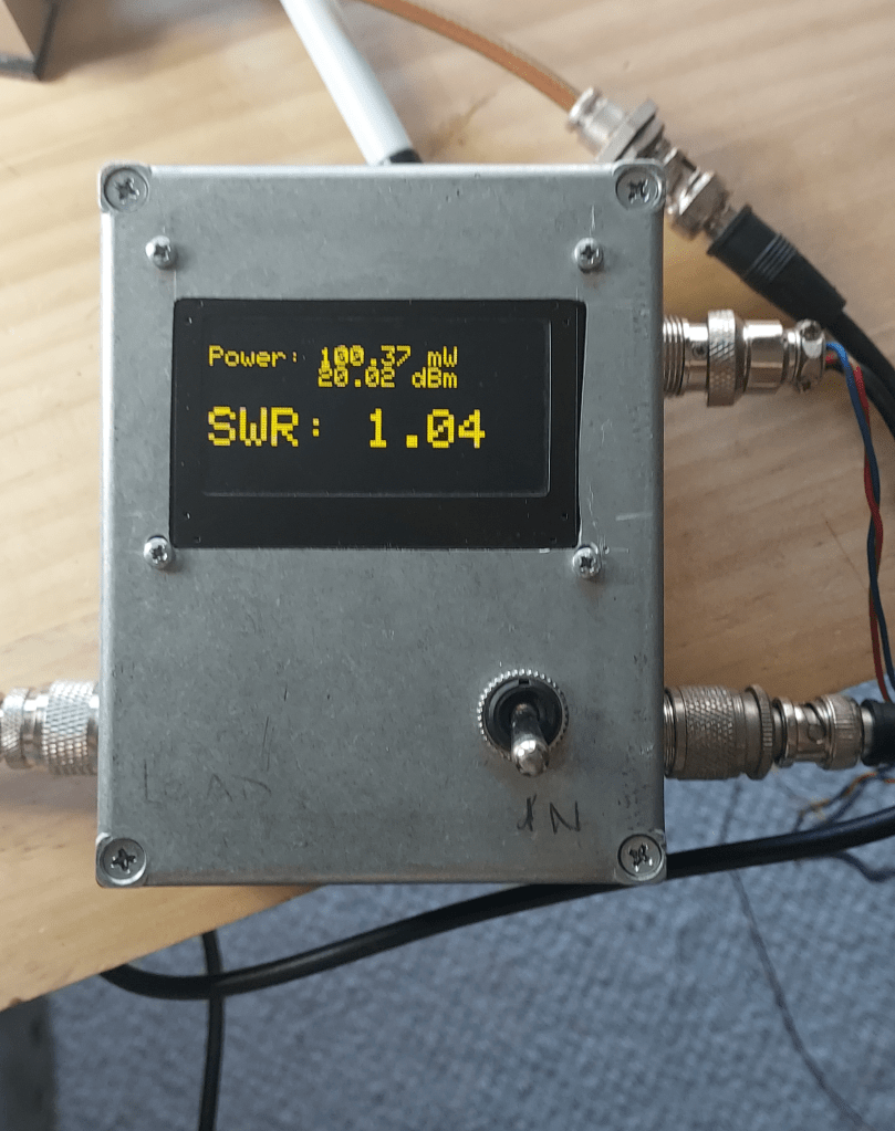
I plan to use an Arduino board, an Adafruit SI5351 module as a tunable signal source and my Power Meter as a detector (see this website)

Using the Antenna

I found the antenna to be very sharp with a bandwidth of 20 KHz or so on 14 MHz

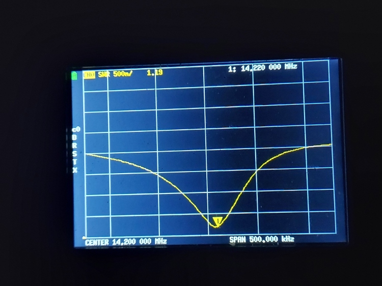
NanoVNA image -SWR on 14 MHz

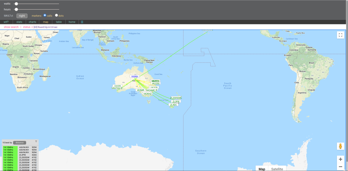
So in practice I had to have some way of tuning it – I used a NanoVNA available from China. There are various copies of this device – the design is Open Source and is being constantly developed. This is a cheap but very capable Vector Network Analyser. It takes some getting used to with the small touch screen interface but it probably impossible to design and build an antenna such as this without such an instrument. So far I have made contacts on 5W SSB to all Australian states from Central Australia on 14 MHz and some contacts on 3.5 MHz from Central Australia – none would be less than 1500KM. Using low power modes such as WSPR and FT-8 on 20 and 30m I have been able to communicate worldwide. I have had less success on 80 and 40m but here I am competing using low power (5W) and noise and high power stations. Match was near perfect on 30m and 20m but less so on the lower bands

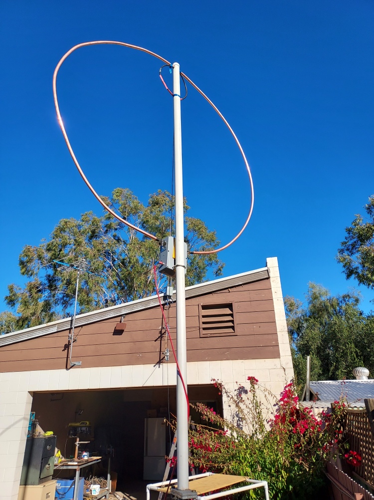
  • The Antenna on a temporary mount for testing

References

(1) Frank Dorenberg N4SPP – a very comprehensive reference. The author has gone to a lot of trouble with experiments and detailed explanations of theory

https://www.nonstopsystems.com/radio/frank_radio_antenna_magloop.htm

(2) Software libraries

https://github.com/pololu/tic-arduino

https://github.com/pololu/pushbutton-arduino

(3) Nano VNA

https://nanovna.com/

(4) Parts for motor drive – these were obtained from Core Electronics

Pololu Tic T825 USB Multi-Interface Stepper Motor Controller (Connectors Soldered)POLOLU-3130
Pololu Universal Aluminum Mounting Hub for 5mm Shaft, M3 Holes (2-Pack)POLOLU-1998
Stepper Motor: Unipolar/Bipolar, 200 Steps/Rev, 42×48mm, 4V, 1.2 A/PhasePOLOLU-1200
Pololu Stamped Aluminum L-Bracket for NEMA 17 Stepper Motors

(5) Arduino sketch

// Stepper motor control of Magnetic Loop Antenna tuning
//
// Variable capacitor which tunes loop can be rotated continuously
// Using Polulu #1200 motor 
// 200 steps/revolution - can be used in microstep mode to 1/32 steps 
// Effective number of steps 3200 as capacitor goes through full adjustment in half a rotation
//
// Using Tic T825 stepper control board in I2C serial mode 
// Motor serial device number must be set to its default value of 14.
//
// Control board Arduino Leonardo with 4 pushbuttons
// normally open on lines 2,3,4,5

// The Tic's control mode must be set to "Serial/I2C/USB".  The
// baud rate should be set to 9600 and CRC should not be enabled.
// This example uses the compact protocol, so the Tic's device
// number is not used, and can be set to anything.

#include <Tic.h>
#include <Pushbutton.h>

Pushbutton buttonA(2);
Pushbutton buttonB(4);
Pushbutton buttonC(5);
Pushbutton buttonD(6);

// Define a variable that we can use to keep track of whether we
// are in speed control or position control mode.
enum class Mode {
  Off,
  Position,
  Velocity
};
auto mode = Mode::Off;

// This is a series of positions to step to, in units of
// microsteps.  Pressing button A makes the stepper motor cycle
// through these positions.
int32_t positionTable[] = {
  0,
  5,
  7,
  35,
  75,
  -100
};

// Keep track of which position in the position table is selected.
uint8_t positionIndex = 0;
// Current position 
uint32_t position = 0;

#define POSITION_TABLE_SIZE (sizeof(positionTable)/sizeof(positionTable[0]))

// On boards with a hardware serial port available for use, use
// that port to communicate with the Tic. For other boards,
// create a SoftwareSerial object using pin 10 to receive (RX)
// and pin 11 to transmit (TX).
#ifdef SERIAL_PORT_HARDWARE_OPEN
#define ticSerial SERIAL_PORT_HARDWARE_OPEN
#else
#include <SoftwareSerial.h>
SoftwareSerial ticSerial(10, 11);
#endif

TicSerial tic(ticSerial);

void setup()
{
   // Need to wait a second or so after powerup to let serial port on
   //TIC controller board to start up 
   // delay(1000);
   // Set the baud rate.
  ticSerial.begin(9600);

  // Give the Tic some time to start up.
  delay(1000);
  
  // Using Tic T825 board  
  tic.setProduct(TicProduct::T825);
  //tic.reset();
  
  // 1/32 step microsteps 
  tic.setStepMode(TicStepMode::Microstep32);
  // Current limit 1000mA
  tic.setCurrentLimit(1000);
  // Max Rotation speed - 400 steps/sec approx 8 sec to do a complete //tune of the antenna
  tic.setTargetVelocity(400000); 
  // Will jump to this speed at start - 50 steps/sec
  tic.setStartingSpeed(50000);
  // Accelerate at 100 steps/sec/sec
  tic.setMaxAccel(10000);
  
       
  // Set the Tic's current position to 0, so that when we command
  // it to move later, it will move a predictable amount.
  // - do this once only with the capacitor set to max
  //tic.haltAndSetPosition(0);
  
  // Tells the Tic that it is OK to start driving the motor.  The
  // Tic's safe-start feature helps avoid unexpected, accidental
  // movement of the motor: if an error happens, the Tic will not
  // drive the motor again until it receives the Exit Safe Start
  // command.  The safe-start feature can be disbled in the Tic
  // Control Center.
  //tic.exitSafeStart();
}

// Sends a "Reset command timeout" command to the Tic.  We must
// call this at least once per second, or else a command timeout
// error will happen.  The Tic's default command timeout period
// is 1000 ms, but it can be changed or disabled in the Tic
// Control Center.
void resetCommandTimeout()
{
  tic.resetCommandTimeout();
}

// Delays for the specified number of milliseconds while
// resetting the Tic's command timeout so that its movement does
// not get interrupted by errors.
void delayWhileResettingCommandTimeout(uint32_t ms)
{
  uint32_t start = millis();
  do
  {
    resetCommandTimeout();
  } while ((uint32_t)(millis() - start) <= ms);
}

// Polls the Tic, waiting for it to reach the specified target
// position.  Note that if the Tic detects an error, the Tic will
// probably go into safe-start mode and never reach its target
// position, so this function will loop infinitely.  If that
// happens, you will need to reset your Arduino.
void waitForPosition(int32_t targetPosition)
{
  do
  {
    resetCommandTimeout();
  } while (tic.getCurrentPosition() != targetPosition);
}

void loop()
{
   if (buttonA.isPressed() && buttonB.isPressed())
  {
         
    // Both button A and button B are pressed.
    // Set current position as zero 
      tic.haltAndSetPosition(0);
  }
  
  if (buttonA.isPressed())
  {
       // Move up in frequency by 200 steps with each press of button B 
 
    digitalWrite(LED_BUILTIN, HIGH);   // turn the data LED on
    tic.energize();
    tic.exitSafeStart();
    mode = Mode::Position;    
    position = tic.getCurrentPosition();
    position = position + 200;
    tic.setTargetPosition(position);    
   
    waitForPosition(position);
    tic.deenergize();
    digitalWrite(LED_BUILTIN, LOW);    // turn the LED off    

  }
  else if (buttonB.getSingleDebouncedPress())
  {
      // Move down in frequency by 200 steps with each press of button B 
 
    digitalWrite(LED_BUILTIN, HIGH);   // turn the data LED on
    tic.energize();
    tic.exitSafeStart();
    mode = Mode::Position;    
    position = tic.getCurrentPosition();
    position = position - 200;
    tic.setTargetPosition(position);    
   
    waitForPosition(position);
    tic.deenergize();
    digitalWrite(LED_BUILTIN, LOW);    // turn the LED off    
  }
  else if (buttonC.getSingleDebouncedPress())
  {
    // Move up 1 step with each press of Button C  
 
    digitalWrite(LED_BUILTIN, HIGH);   // turn the data LED on
    tic.energize();
    tic.exitSafeStart();
    mode = Mode::Position;
    position = tic.getCurrentPosition();
    tic.setTargetPosition(position + 1);
    //waitForPosition(position+1);
    
    // If the button is still pressed - continue to move one step at a time
    delay(100);
    while (buttonC.isPressed())
    {
        position = tic.getCurrentPosition();
        tic.setTargetPosition(position + 1);
        //waitForPosition(position+1);
    }
    // 
    tic.deenergize();
    digitalWrite(LED_BUILTIN, LOW);    // turn the LED off    
    

  }
    else if (buttonD.getSingleDebouncedPress())
  {
    // Move down one step with each press of Button D 
 
    digitalWrite(LED_BUILTIN, HIGH);   // turn the data LED on
    tic.energize();
    tic.exitSafeStart();
    mode = Mode::Position;
    position = tic.getCurrentPosition();
    tic.setTargetPosition(position-1);
    //waitForPosition(position-1);
    // If the button is still pressed - continue to move one step at a time
    delay(100);
    while (buttonD.isPressed())
    {
        position = tic.getCurrentPosition();
        tic.setTargetPosition(position - 1);

    }    
 
    tic.deenergize();
    digitalWrite(LED_BUILTIN, LOW);    // turn the LED off    
  }
}


/*  // Use debouncing to detect distinct presses of button A.
  if (buttonA.getSingleDebouncedPress())
  {
    // Button A was pressed.
    // Advance to the next position in the table.
    positionIndex++;
    if (positionIndex >= POSITION_TABLE_SIZE)
    {
      positionIndex = 0;
    }
    tic.setTargetPosition(positionTable[positionIndex]);
    tic.exitSafeStart();
    mode = Mode::Position;
  }

  // Prevent the command timeout error from happening.
  tic.resetCommandTimeout();

*/
//}

High Performance Power/SWR Meter

A Wide Dynamic Range Power/SWR meter using a Directional Coupler, AD8307 Log Amplifier and Arduino Microcontroller

Anyone experimenting with antennas or Power Amplifiers will need to measure RF power at some point. Indeed, Radio Amateurs should have some means of measuring RF power to ensure they are operating within their Licence conditions. Standing Wave Ratio (SWR) is a good measure of antenna matching and performance. Power amplifiers in general dont take kindly to operating into a significant load mismatch, so it is useful to be able to measure SWR. Low power Digital modes such as WSPR and FT8 are using power levels in the milliwatts.

Various designs have been published over the years. One approach is to use two striplines parallel to the main conductor with a load and detector at opposite ends. These are simple but have the drawback that they are heavily frequency dependent, so they have to be calibrated for each band. (ref)

Another approach is to use a directional coupler. These can be made frequency independent over a relatively wide range. From a theory point of view there are 4 ports. The input and output ports are connected with a relatively small loss – approx 0.1dB at 3.5 MHz rising to 0.4dB at 50 MHz in this case. The input port couples “forward” power to the forward port with attenuation determined by the “current” mode transformer. With good design the reflected port is not coupled to the input port. It sees “reverse” power reflected from the load by impedance mismatch. For HF use these transformers can be constructed using ferrite cores.

In this project I have modified a design by K6JCA as a high performance, high power directional coupler. (Fig 1 – ref)

Fig 1 Directional Coupler – from KJ6CA article

The design uses two ferrite toroid transformers to yield forward and reverse power. Coaxial cable passes through the toroid as a primary. The output to forward and reverse ports is attenuated by the ratio of the turns on this transformer. In this case a 24:1 ratio yields 27dB attenuation in the forward direction. There is a pi network attenuator after this to yield a final attenuation before the detectors of 52dB. Thus a forward power of 2KW will yield an output of +11dBm at the detector.

The ferrite cores used in this design must be able to tolerate the power and flux density at the power levels expected. The ferrite can be irreversibly damaged if it is exposed to power levels exceeding its rating. Flux density and inductance varies with frequency – KJ6CA discusses this at length in his article. I have used type 43 ferrite toroids – the “current” mode transformer can use a smaller core with only 1 turn of high power through it. In my case I reversed the polarities of the transformers to his article.

The Detector

Many designs for Power/SWR meters use a diode detector. This is a simple solution but dynamic range is limited due to the forward voltage drop of the diode. This can be reduced by the use of Germanium diodes – but these are hard to find nowadays. Typically these bridges will need several watts input power to produce a useful reading. Many digital modes such as WSPR are now using power levels down to milliwatts. Also it is useful to be able to measure low power levels in the development of systems.

If a logarithmic detector such as those produced by Analog Devices (AD8310, AD8307) is used, power can be measured over a much wider dynamic range. These devices will give an output proportional to log(power) of approx 20mV/dB over the range -70 to +10 dBm, and with a frequency range of audio up to 500 MHz or so. With the attenuators in this design this translates to a dynamic range of approximately -20 to +60dBm (10uW to 1KW). The board uses separate AD8307 log detectors for forward and reverse power. With advances in package types the older packages (SOIC8) are now obselete and hard to find – I sourced some from a Chinese supplier on EBay. While these are surface mount and pins with 1.25 mm spacing, It is possible for a hobbyist to solder these packages by hand. Many of the new package types are microscopic and can only be soldered with a heat gun or oven and solder paste. In fact, I have used surface mount components for this whole design. I find if anything these are easier to deal with than through hole components. You do need magnification and a good soldering setup however.

SWR Measurement

SWR is a measure of the ratio of forward vs reverse power reflected back from a load. If the match is perfect there will be no reflected power and SWR will be 1.00. If there is a complete mismatch (eg short or open circuit) then the SWR will be infinite.

The formula for SWR is

Where: Pr = Reverse power, Pf = forward power (W)

The actual SWR is calculated according to the formula above by the Arduino microcontroller after converting the analog outputs of the AD8307 devices to a digital quantity.

Microcontroller

The Microcontroller handles Analog to Digital Conversion of the AD8307 outputs, calculations and driving an OLED high brightness display. As this is a relatively simple task I have used a small microcontroller with ADC inputs and suitable 3.3V logic outputs. The Arduino ecosystem now has many possible board and interface options and boards are cheap and easily available. There is an easy to use Development Environment (IDE) and libraries for many tasks. The board has a USB interface for easy programming. Why reinvent the wheel?

I had some problems with one board with programming – this appeared to be related to either fuses or the reset circuit – I never did work it out. I settled on the Adafruit Trinket Pro 3V3 – this is a small module for which I have designed a “component” in KICAD. The module then is another component in the circuit. It does not have a Serial interface via USB – you have to be creative in debugging software! Be aware that the chip must be reset when programming – this is not made particularly clear in the documentation.

I have used extensive bypassing and inductors for low pass filters on the board. I have not tested it with high power – it is possible that the strong RF fields involved will upset the micro logic – it may be necessary to shield the RF section in this case.

Circuit Fig 2

PCB Drafting

I used KICAD to draft a double sided PCB for the project – the Schematic and PCB will be available at Github. For those who want to make their own boards, a Gerber package can be sent to a PCB manufacturer such as JLPCB

Display

I am still developing the software for a suitable display – I plan to use a large high brightness OLED displays. There have been supply problems recently. The current software works with a small 1 inch OLED and I2C as the interface. Software will be available on Github also – see references

Transformers

The transformers T1 and T2 form the heart of the Directional Coupler. I have used No 43 ferrite which has suitable characteristics for the frequencies concerned, though the response does start to fall off above 25MHz. A 24:1 turns ratio is the equivalent of a 576:1 impedance transformation. If the secondary was loaded with a (50 X 576 = 28800) ie 28.8K load full power would be transferred to the load, assuming a perfect transformer. But in our case we are loading the secondary with 50 Ohms – the transformer then becomes an attenuator with an attenuation of 577 times. If the we calculate that in decibels it is 10 Log (577) = 27.6 dB

The primary is a single “turn” of RG213 Coax passing through the centre of the core. TI acts as a “current” transformer and T2 as a “voltage” transformer. The outer braid of the RG213 is grounded at one end only.

The secondary is 24T of 20 SWG wire – see Fig 3

Fig 3 Transformer Schematic

The Code

Source is available on Github

I have extended the basic setup() and loop() functions in the basic Arduino IDE with classes for the meter and display

In brief the code initializes the display and then enters a loop. Forward and reverse measurements are averaged over a number of points and the peak value in dBm and watts displayed. SWR is calculated according to the formula above and displayed in similar fashion.

Corrections for offset and system gain can be adjusted in software to get quite accurate measurements over a wide range, approaching the resolution of the meter. I did this by trial and error by first correcting the change for each 10 dB (using my HP8640B as a source) and then adjusting the zero correction for 0dBm

Results

I used my faithful HP8640B Signal Generator as a reference for the power measurements.

The output from the signal generator appears to correlate well with the indication on my Tek MSO3304 Oscilloscope/Spectrum Analyser. If you do not have access to a calibrated power source it is possible to derive power using an oscilloscope to measure the voltage across a 50 ohm load and build attenuators to derive lower power levels. To make these attenuators, I use surface mount components, SMA connectors and scraps of double sided PC board. One side of the board acts as a groundplane. Using a sharp tool such as a glass cutter, score lines in the board to create pads for the attenuator. This is a quick and economical method for simple circuits such as this. SMA coaxial connectors and leads are available cheaply on E bay. The best way to buy SM resistors is to buy a development kit of many values available from various suppliers. The standard size nowadays is 0805. You will need a pair of fine forceps to handle these – as my day job is medical I have acquired tissue forceps of the “Adson” plain pattern – these seem ideal for this work. You will need a clean workspace with good lighting and magnification.

There are various sites on the web to derive values for 50 ohm attenuators.

The Power meter has a resolution of approx 0.25dB Note that the power measurement assumes a 50 Ohm load – in fact the device is measuring voltage and deriving power from this.

Minimum usable power level measurement appeared to be in the order of -30dBm. I have not tested the max output as I dont have a 2KW RF source!

The output from my FT818 was as expected

References

Stripline Power/SWR Meter – one design is at

https://hevirred.blogspot.com/2014/01/

Wideband HF Directional Coupler

https://k6jca.blogspot.com/2015/07/antenna-auto-tuner-design-part-5.html

AD8307 Datasheet

Click to access AD8307.pdf

KICAD Open Source PCB drafting software

https://www.kicad.org/

Source Code and KICAD files

https://github.com/richardhosking/SWR-Power-Meter

WSPR and FT8 with the FT817 and Digirig

Digital Modes have become popular in recent years. WSPR (Weak Signal Propagation Reporter) is a system devised by Joe Taylor K1JT which uses very narrow bandwidth (6Hz) and slow data rates. This allows signals to be decoded that are very low amplitude and not audible to a human operator. A network of automated receivers has been set up around the world – signals heard are automatically logged to a database accessible on the internet. It means that antennas can be tested and propagation estimated using low power down to a few milliwatts.

FT8 is a 2 way mode where operators can communicate using semiautomated messages. It again uses narrow bandwidth and slow datarates – messages are limited to 15 characters. It occupies just 2.5KHz of each band and there may be many contacts occurring at once

The Yaesu FT817 has a deserved reputation as a rugged reliable portable multiband multimode transceiver. It is low power with a maximum output of 5W and can be configured in Digital modes making it an ideal candidate for this work.

Many operators report using Windows for the WSPR Software – I am a dedicated Linux zealot and I use Linux Mint 19 as an easy to use Desktop

To Interface between the computer and the radio I purchased a Digirig from Denis Grizak – this device is excellent value at <AUS$100 for the unit plus connecting cords. The design is open source and uses a standard USB interface and audio CODEC

However setting all this up was not seamless – there are a few issues to sort out.

Software

The original software was WSJT – the latest version is called WSJTX and we are now up to version 2.5.4. This is a nicely constructed program with all the relevant options and automation for a noob built in. All the common digital modes can be run with the click of a mouse. Windows tends to load versions of all the dependencies (other programs used) with the file – this creates a lot of “bloat” but does mean that you dont have to keep track of dependencies. In Linux the program calls many other programs which have to be the correct version – you can end up in “dependency hell” if you simply load the latest WJSTX using sudo dpkg as suggested. This may be fixed using sudo apt install -f which usually (but not always) manages all the dependencies. As it happens the latest version of wjst-x is available in the Linux Mint Software manager as a “flatpack” (dont use the other option which is version 1.1) – this loaded without difficulty.

Interface

The interface converts audio from the radio to a USB stream for processing, sends an audio signal to the radio for transmit via USB and controls the digital (CAT) interface of the radio to set frequency and mode and to key the transmitter. Check that your computer can see the interface after plugging it in with lsusb in a terminal. You should see the interface listed with three USB endpoints – one for the digital CAT interface, one for the PTT and one for the Audio CODEC.

(base) richard@MillsSt:~$ lsusb
Bus 002 Device 002: ID 8087:0024 Intel Corp. Integrated Rate Matching Hub
Bus 002 Device 001: ID 1d6b:0002 Linux Foundation 2.0 root hub
Bus 001 Device 005: ID 8087:07da Intel Corp.
Bus 001 Device 004: ID 0458:00cc KYE Systems Corp. (Mouse Systems)
Bus 001 Device 003: ID 04d9:1603 Holtek Semiconductor, Inc. Keyboard
Bus 001 Device 002: ID 8087:0024 Intel Corp. Integrated Rate Matching Hub
Bus 001 Device 001: ID 1d6b:0002 Linux Foundation 2.0 root hub
Bus 004 Device 001: ID 1d6b:0003 Linux Foundation 3.0 root hub
Bus 003 Device 004: ID 10c4:ea60 Cygnal Integrated Products, Inc. CP210x UART Bridge / myAVR mySmartUSB light
Bus 003 Device 003: ID 0d8c:013c C-Media Electronics, Inc. CM108 Audio Controller
Bus 003 Device 002: ID 0424:2412 Standard Microsystems Corp.
Bus 003 Device 001: ID 1d6b:0002 Linux Foundation 2.0 root hub

Sometimes Linux protests with sending data out to USB devices – this is a potential security risk – the flatpack obviously managed all the issues of groups and permissions in my case

You may have to make the USB device a member of the “dialout” group and give it suitable permissions – see the web for how to do this.

I managed to destroy one of the cords with the device thinking the two were the same – but they have different miniDIN connectors so I had to do a bit of rebuilding. It is certainly worth buying the cords ready made – these miniDIN connectors are small!

The DATA connector accepts audio in to the microphone for the USB CODEC to Pin 1 Data In

Pin 5 Data Out is audio from the receiver. At the USB interface end there is a 3.5mm stereo plug – Data Out goes to the tip, Data In goes to the ring and GND is connected to the sleeve – see Digirig site for details. This plug goes to “AUDIO” on the Digirig

Excerpt from Yaesu FT817 manual

The ACC connector has a similar arrangement with a stereo plug connecting to GND, RXD and TXD connecting to SERIAL on the Digirig

Setting up the Radio

Check the User manual for details – there are more than 50 option menus for the FT817

The CAT software will set up frequency and mode

Mode Digital

Press the F key for a second or so to enter the detailed menus

Use the select knob for various options

03 9600 Mic  – this is the data input (or was it option 25 or 39? – there seem to be various digital mic inputs – I set this to 75

14 CAT rate  38400

25 Dig Mic – 50

26 Dig Mode User -U

27 Dig shift 0 Hz

39 PKT Mic 75

45 SQL/RF RF-Gain

Set the RF gain to near max

Press the F key again to save options

In my case

I ran the radio at low power nominally 1 W though my power meter indicated 400mW

Setting up the interface options in the WJST-X software (version 2.5.4)

Open the program and go to File => Settings

This opens a dialog with multiple tabs

In the General tab enter your Callsign and Maidenhead locator

In the Radio tab select FT817 under Rig – there are many options here

Under CAT Control select the correct interface port – in my case it was /dev/ttyUSB0 but if you have other USB devices connected it may be different.

Under Serial Port parameters Select Baud Rate 38400 8 bits 2 stop bits no handshake

PTT Method should be set to CAT

toggle the “test CAT” button – if all is well it should turn green after a few seconds

It it goes red or does nothing you have a problem!

Start troubleshooting from one end to the other in a logical manner

Under the Audio Tab select appropriate input and output interfaces for your computer – these will be probably have “C-Media Electronics, Inc. CM108 Audio Controller” in them somewhere and be a USB PnP interface

Note that you have to do additional adjustments in the sound interfaces for levels

There are several other tabs – I did not change the defaults

Setting up the computer audio

Go to the sound setup menu of the computer

Select Audio In as the USB PnP device and the same for audio out

The audio level should be set so that the WJST-X software is not overloaded – it has a receive level indicator – this should indicate approx 50 dB with normal operation – if it is red reduce audio level for the input device

Similarly for the mic level – you may have to adjust this so the radio is not overloaded – set it and the data mic level in the radio so that ALC is starting to act

Note that you may have to specify “stereo” on the computer output device to get audio to the radio microphone

Operation

There are many posts on the web re actual operation in these modes

I found WSPR interesting to test antennas and propagation at various times of the day on various bands

I found the database at the new VK7JJ site wspr.rocks useful for tracking contacts on WSPR

Experiments with Rotary Encoders

Rotary encoders can be used similarly to potentiometers. The difference being that an encoder has full rotation without limits (It just goes round and round). They output gray code so that you can tell how much and in which direction the encoder has been turned. They’re great for navigating menu screens and things like that. (Core Electronics )

Trying one of these for a radio project – 3 rotary encoder pins only

I could not get it to work with the software discussed (there seem to be a lot of solutions around!)

With experimentation I found there were a number of issues

Pinouts

The datasheet for the device I started with did not have a pinout though I did find it elsewhere in the device description. The common pattern appears to be 3 pins – the centre pin common and the end pins A and B

However this device had one end pin as common and the other two as A and B.

Check the datasheet! (In this case it was incorrect)

A second device I tried had the usual pinout.

Mode of operation.

The datasheet (in part) for the first device I had showed that the output should be a Quadrature Gray code with rotation of the encoder.

But between detents, A and B were not connected to ground and were high due to a pullup I had installed If I watched the output on a CRO, I get a brief transition Hi=>Lo with each detent of the encoder of about 30msec for the A pin. Both pins are otherwise HIGH all the time. The B pin goes low immediately for CCW rotation – there did not appear to be a delay between A and B lines (as shown on the oscilloscope). With the typical noise requiring debouncing this could be an issue.

CRO Tek MDO3014 capturing one encoder movement detent to detent

For CW rotation the Hi=> Lo transition of the B pin is delayed by about 10-15msec

Mechanically this device was a switch with contacts between ground and each line as the device was rotated with a full momentary Gray code sequence between each detent.

I tried a second rotary encoder from Jaycar
The display below shows the output when rotating this rapidly
Screenshot (ignore the frequency readout )

The two seem to be roughly in quadrature – but with this device the lines stayed both high or both low between detents – ie a half Gray Code step per detent.

There was an interesting discussion on the Arduino Forum at at Purchased my first Rotary Encoders. faulty or not? – #10 by system – General Electronics – Arduino Forum
Encoders were behaving like the one I have described above – ie at each detent both switches open circuit but making brief contact between detents – these appear to follow a Gray Code sequence between detents but are open circuit at “rest” – presumably to save pullup current

Without fairly sophisticated test gear and knowledge a noob will not be able to work all this out
So it appears there are several Variants
(1) Different Pinouts
(2) Transient make/break between detents
(3) Both pins changing state between detents – they do seem to follow a Gray code in between – a half step per detent (the JayCar decoder)
(4) Encoders generating pulses rather than a true “Gray Code” sequence as in the ones above – this may a poor quality or faulty encoder.

And then the Software…

In practice the software will probably handle most of these variations.

The first problem to deal with is switch “bounce”. A typical mechanical contact may take 20msec or more to settle as it makes contact – there may be many on/off transitions as it does so. In this case the encoder continues to rotate – there may be more switch noise as it does so. Of course , a microcontroller is fast enough to see these transitions and may interpret them as “true” data.

There are various approaches to this problem

A Hardware Filter such as a lowpass RC network can be installed on the encoder data lines. This has the disadvantage of additional components and will slow the encoder response. A Delay in software will save the components but still has the problem of slowing the system.

The most durable approach appears to be a State Machine in software

A change in one of the data lines triggers an interrupt which reads the data lines

The routine then checks whether the transition is a valid Gray code sequence and then whether it is clockwise or anticlockwise – each step effectively filters invalid data transitions. This routine appears to work well. It is fast and appears to tolerate various decoders without error

Here is code for such a routine in C++ for the Arduino Uno

// Rotary encoder variables
// Indicates status of last ISR
volatile unsigned char state; 
  
// Lookup table whether transition is valid Gray Code
uint8_t rot_enc_table[] = {0,1,1,0,1,0,0,1,1,0,0,1,0,1,1,0};

/* ISR (Interrupt service routine) 
* for Rotary encoder
* for the Arduino must have no parameters
*  and no return
* Cannot call Class members it seems
*/
void encoder(void){

    // left shift last prevNextCode 2 bits
    prevNextCode <<= 2;

   // read in current state of input pins
   // to prevNextCode bits 1 and 0
    if (digitalRead(rotA)) prevNextCode |= 0x02;
    if (digitalRead(rotB)) prevNextCode |= 0x01;

    /* Mask off upper 4 bits
    * prevNext Code now holds
    * current and previous state of the input pins
    * in its lower 4 bits 
    */
    prevNextCode &= 0x0f;

    /* Use this as a key to rot_enc_table
    * valid transitions between this state
    *  and last will return 1  - invalid 0 
    * according to a Gray Code sequence
    * If valid then store as 8 bit data in store
    * store now holds this and the last valid transition
    */
    if  (rot_enc_table[prevNextCode]){
        store <<= 4;
        store |= prevNextCode;

    /* now decide whether the transition was 
    * clockwise or counterclockwise
    * effectively a further "debounce" stage
    * store encodes the last 2 transitions
    * in sequence of a complete cycle from 00 to 11
    * or vice versa
    * for encoders with a half cycle from 00 to 11
    *  and 11 to 00 between detents 
    * If the high bit changed first => CW
    */
        if ((store&0xff)==0xD4 | (store&0xff)==0x2B){
           state = 2;
     }
    //  If the low bit changed first => CCW 
        else if ((store&0xff)==0xE8 | (store&0xff)==0x17){
            state = 1;
   }
    // If no valid transitions return 0
    else{
       state = 0;
    }
  }
}