A Wide Dynamic Range Power meter using a Directional Coupler, AD8307 Log Amplifier and Arduino Microcontroller

Anyone experimenting with antennas or Power Amplifiers will need to measure RF power at some point. Indeed, Radio Amateurs should have some means of measuring RF power to ensure they are operating within their Licence conditions. Standing Wave Ratio (SWR) is a good measure of antenna matching and performance. Power amplifiers in general dont take kindly to operating into a significant load mismatch, so it is useful to be able to measure SWR. Low power Digital modes such as WSPR and FT8 are using power levels in the milliwatts.
Various designs have been published over the years. One approach is to use two striplines parallel to the main conductor with a load and detector at opposite ends. These are simple but have the drawback that they are heavily frequency dependent, so they have to be calibrated for each band. (ref)
Another approach is to use a directional coupler. These can be made frequency independent over a relatively wide range. From a theory point of view there are 4 ports. The input and output ports are connected with a relatively small loss – approx 0.1dB at 3.5 MHz rising to 0.4dB at 50 MHz in this case. The input port couples “forward” power to the forward port with attenuation determined by the “current” mode transformer. With good design the reflected port is not coupled to the input port. It sees “reverse” power reflected from the load by impedance mismatch. For HF use these transformers can be constructed using ferrite cores.
In this project I have modified a design by K6JCA as a high performance, high power directional coupler. (Fig 1 – ref)
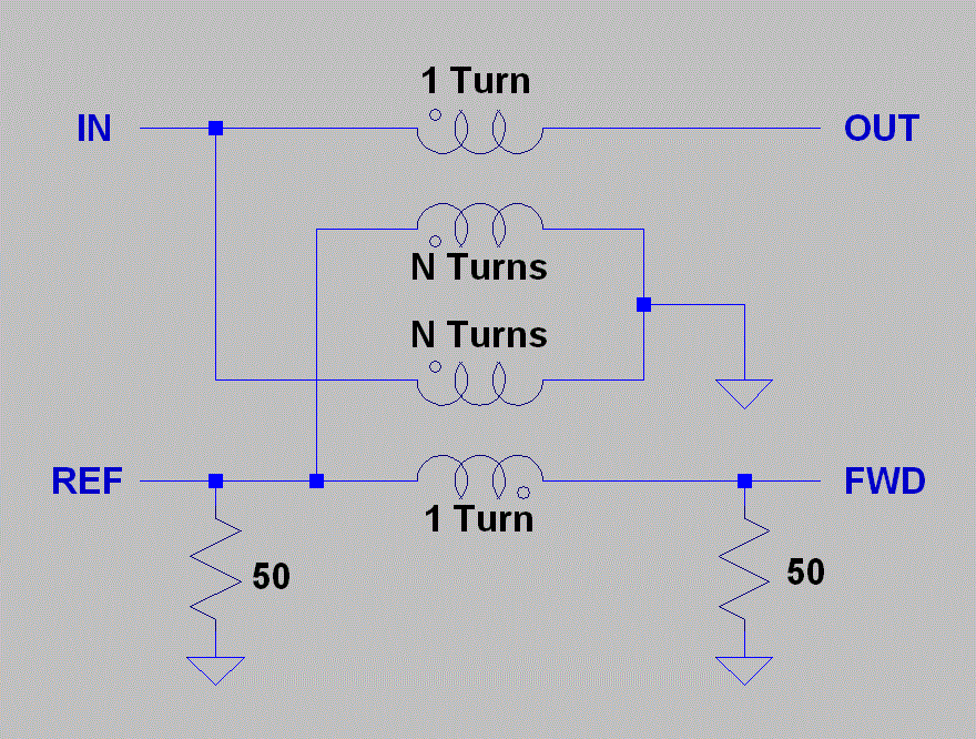
Fig 1 Directional Coupler – from KJ6CA article
The design uses two ferrite toroid transformers to yield forward and reverse power. Coaxial cable passes through the toroid as a primary. The output to forward and reverse ports is attenuated by the ratio of the turns on this transformer. In this case a 24:1 ratio yields 27dB attenuation in the forward direction. There is a pi network attenuator after this to yield a final attenuation before the detectors of 52dB. Thus a forward power of 2KW will yield an output of +11dBm at the detector.
The ferrite cores used in this design must be able to tolerate the power and flux density at the power levels expected. The ferrite can be irreversibly damaged if it is exposed to power levels exceeding its rating. Flux density and inductance varies with frequency – KJ6CA discusses this at length in his article. I have used type 43 ferrite toroids – the “current” mode transformer can use a smaller core with only 1 turn of high power through it. In my case I reversed the polarities of the transformers to his article.
The Detector
Many designs for Power/SWR meters use a diode detector. This is a simple solution but dynamic range is limited due to the forward voltage drop of the diode. This can be reduced by the use of Germanium diodes – but these are hard to find nowadays. Typically these bridges will need several watts input power to produce a useful reading. Many digital modes such as WSPR are now using power levels down to milliwatts. Also it is useful to be able to measure low power levels in the development of systems.
If a logarithmic detector such as those produced by Analog Devices (AD8310, AD8307) is used, power can be measured over a much wider dynamic range. These devices will give an output proportional to log(power) of approx 20mV/dB over the range -70 to +10 dBm, and with a frequency range of audio up to 500 MHz or so. With the attenuators in this design this translates to a dynamic range of approximately -20 to +60dBm (10uW to 1KW). The board uses separate AD8307 log detectors for forward and reverse power. With advances in package types the older packages (SOIC8) are now obselete and hard to find – I sourced some from a Chinese supplier on EBay. While these are surface mount and pins with 1.25 mm spacing, It is possible for a hobbyist to solder these packages by hand. Many of the new package types are microscopic and can only be soldered with a heat gun or oven and solder paste. In fact, I have used surface mount components for this whole design. I find if anything these are easier to deal with than through hole components. You do need magnification and a good soldering setup however.
SWR Measurement
SWR is a measure of the ratio of forward vs reverse power reflected back from a load. If the match is perfect there will be no reflected power and SWR will be 1.00. If there is a complete mismatch (eg short or open circuit) then the SWR will be infinite.
The formula for SWR is

Where: Pr = Reverse power, Pf = forward power ![]()
The actual SWR is calculated according to the formula above by the Arduino microcontroller after converting the analog outputs of the AD8307 devices to a digital quantity.
Microcontroller
The Microcontroller handles Analog to Digital Conversion of the AD8307 outputs, calculations and driving an OLED high brightness display. As this is a relatively simple task I have used a small microcontroller with ADC inputs and suitable 3.3V logic outputs. The Arduino ecosystem now has many possible board and interface options and boards are cheap and easily available. There is an easy to use Development Environment (IDE) and libraries for many tasks. The board has a USB interface for easy programming. Why reinvent the wheel?
I had some problems with one board with programming – this appeared to be related to either fuses or the reset circuit – I never did work it out. I settled on the Adafruit Trinket Pro 3V3 – this is a small module for which I have designed a “component” in KICAD. The module then is another component in the circuit. It does not have a Serial interface via USB – you have to be creative in debugging software! Be aware that the chip must be reset when programming – this is not made particularly clear in the documentation.
I have used extensive bypassing and inductors for low pass filters on the board. I have not tested it with high power – it is possible that the strong RF fields involved will upset the micro logic – it may be necessary to shield the RF section in this case.
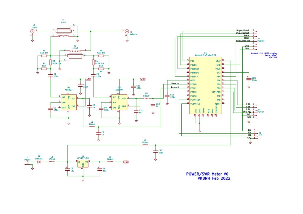
Circuit Fig 2
PCB Drafting
I used KICAD to draft a double sided PCB for the project – the Schematic and PCB will be available at Github. For those who want to make their own boards, a Gerber package can be sent to a PCB manufacturer such as JLPCB
Display
I am still developing the software for a suitable display – I plan to use a large high brightness OLED displays. There have been supply problems recently. The current software works with a small 1 inch OLED and I2C as the interface. Software will be available on Github also – see references
Transformers
The transformers T1 and T2 form the heart of the Directional Coupler. I have used No 43 ferrite which has suitable characteristics for the frequencies concerned, though the response does start to fall off above 25MHz. A 24:1 turns ratio is the equivalent of a 576:1 impedance transformation. If the secondary was loaded with a (50 X 576 = 28800) ie 28.8K load full power would be transferred to the load, assuming a perfect transformer. But in our case we are loading the secondary with 50 Ohms – the transformer then becomes an attenuator with an attenuation of 577 times. If the we calculate that in decibels it is 10 Log (577) = 27.6 dB
The primary is a single “turn” of RG213 Coax passing through the centre of the core. TI acts as a “current” transformer and T2 as a “voltage” transformer. The outer braid of the RG213 is grounded at one end only.
The secondary is 24T of 20 SWG wire – see Fig 3
Fig 3 Transformer Schematic
The Code
Source is available on Github
I have extended the basic setup() and loop() functions in the basic Arduino IDE with classes for the meter and display
In brief the code initializes the display and then enters a loop. Forward and reverse measurements are averaged over a number of points and the peak value in dBm and watts displayed. SWR is calculated according to the formula above and displayed in similar fashion.
Corrections for offset and system gain can be adjusted in software to get quite accurate measurements over a wide range, approaching the resolution of the meter. I did this by trial and error by first correcting the change for each 10 dB (using my HP8640B as a source) and then adjusting the zero correction for 0dBm
Results
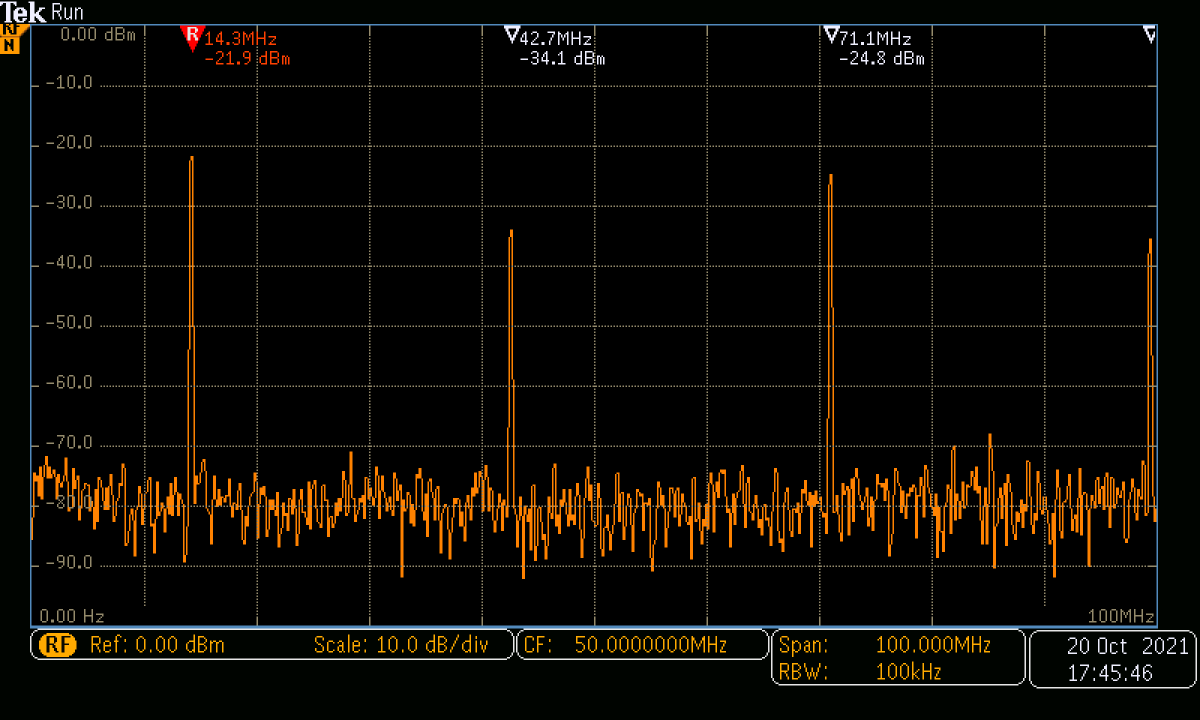
I used my faithful HP8640B Signal Generator as a reference for the power measurements.
The output from the signal generator appears to correlate well with the indication on my Tek MSO3304 Oscilloscope/Spectrum Analyser. If you do not have access to a calibrated power source it is possible to derive power using an oscilloscope to measure the voltage across a 50 ohm load and build attenuators to derive lower power levels. To make these attenuators, I use surface mount components, SMA connectors and scraps of double sided PC board. One side of the board acts as a groundplane. Using a sharp tool such as a glass cutter, score lines in the board to create pads for the attenuator. This is a quick and economical method for simple circuits such as this. SMA coaxial connectors and leads are available cheaply on E bay. The best way to buy SM resistors is to buy a development kit of many values available from various suppliers. The standard size nowadays is 0805. You will need a pair of fine forceps to handle these – as my day job is medical I have acquired tissue forceps of the “Adson” plain pattern – these seem ideal for this work. You will need a clean workspace with good lighting and magnification.
There are various sites on the web to derive values for 50 ohm attenuators.
The Power meter has a resolution of approx 0.25dB Note that the power measurement assumes a 50 Ohm load – in fact the device is measuring voltage and deriving power from this.
Minimum usable power level measurement appeared to be in the order of -30dBm. I have not tested the max output as I dont have a 2KW RF source!
The output from my FT818 was as expected
References
Stripline Power/SWR Meter – one design is at
https://hevirred.blogspot.com/2014/01/
Wideband HF Directional Coupler
https://k6jca.blogspot.com/2015/07/antenna-auto-tuner-design-part-5.html
AD8307 Datasheet
KICAD Open Source PCB drafting software
Source Code and KICAD files
https://github.com/richardhosking/SWR-Power-Meter
