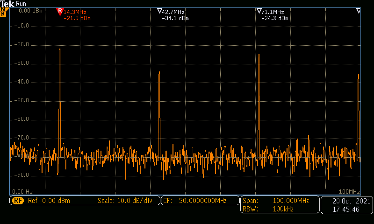

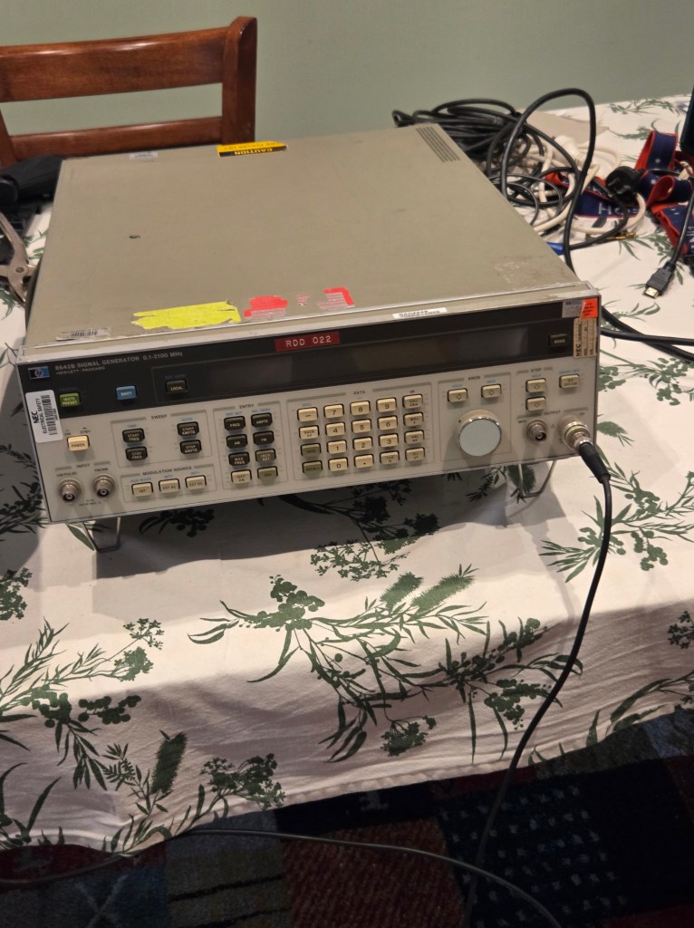
I recently acquired one of these – in the 80s it was the absolute pinnacle of signal generators. Frequency range synthesized 0.1 to 2100 MHz, resolution to 1 Hz, amplitude range -140 to +20 dBm, high spec frequency reference, phase noise best in class, sweep capability. It can certainly do most things I want for homebrewing.
But these things are MASSIVE – 35 kg and long enough to hang over all but the widest of benches. Inside they are a maze of cast metal boxes connected by hardline. And they have a common fault – the display is an early LCD type with a backlight of two small incandescent globes – these fail after a few hundred hours. While the instrument is still usable, the display is difficult to see without a backlight. You would have thought that HP in all its diligence in design in such a high end instrument would make these easy to replace. But clearly this part of the design was beneath the dignity of those high end RF and digital engineers – maybe it was assigned to a relative junior? Yes the backlight works well enough but replacing the globes is not for the faint hearted.
Access
Well perhaps I spoke too soon – HP in its wisdom has made the front panel hinged to swing out allowing access to the microprocessor board and display.
Start by taking out the plastic strip covering the front panel securing screws.
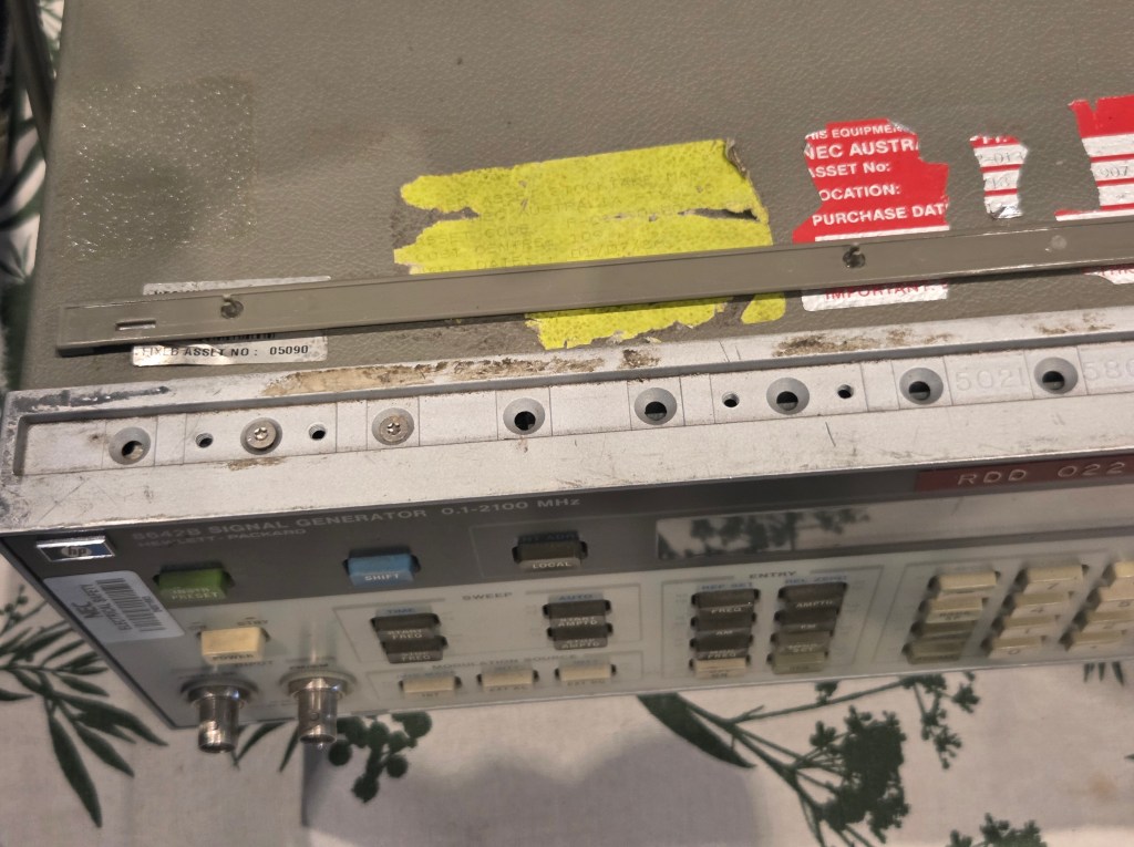
Undo 5 screws securing the front panel top and bottom – leave the left hand end screws which secure the hinges. Here we encounter the first problem – the screw heads have a TORX type key. As it happens I had a suitable driver.
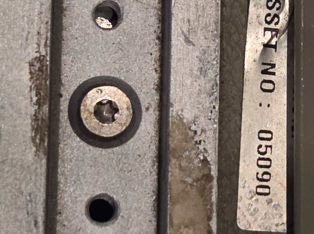
Leave the screws under the feet on the bottom of the case, though it is helpful to remove the feet.
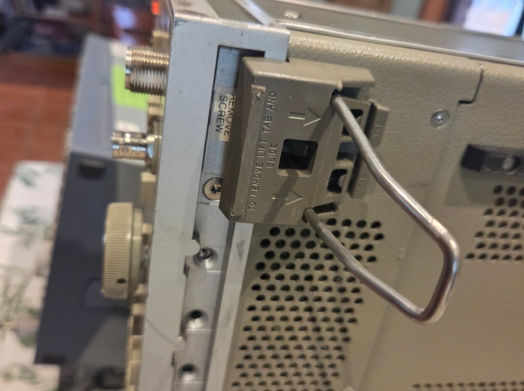

The front panel with display will swing outwards.
Remove the metal shield and with lugs securing the coaxial cable to the audio modulation generator output.

Undo the nuts securing the board A2 to the front panel and ease the board away from the panel by a few inches.
Other posters on this topic remove the A2 board entirely – I was able to get the display module A2A1 out by carefully easing its connectors at either end the board apart and leaving the main board in situ.
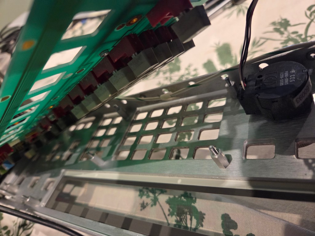
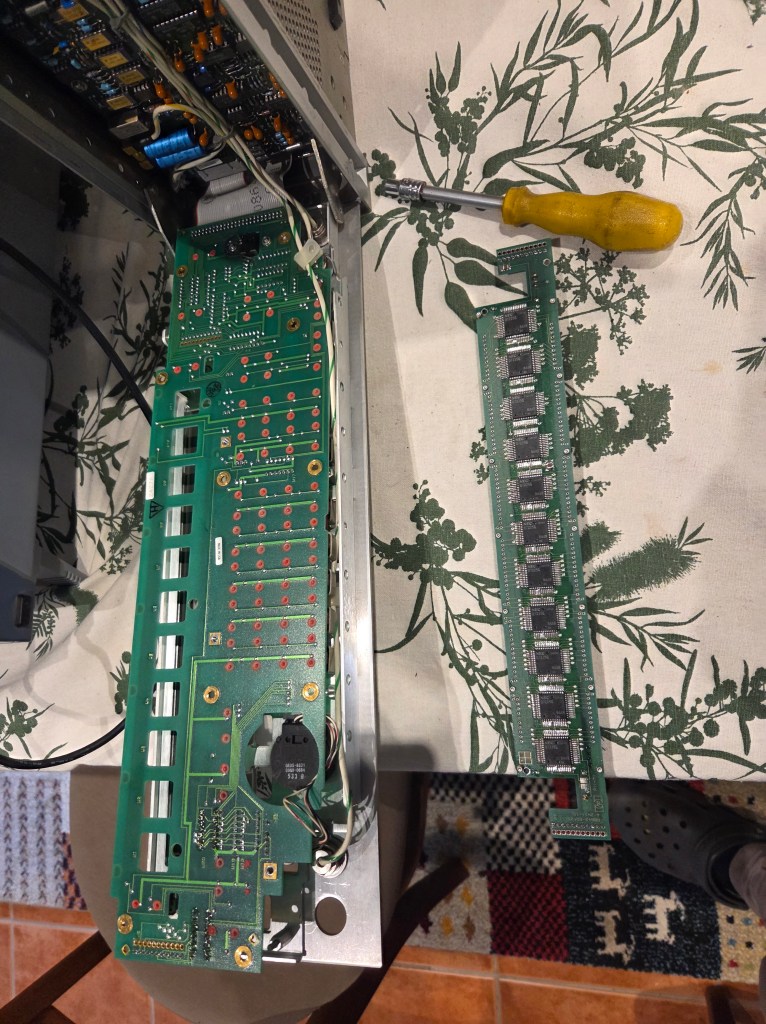
With the display module now on the bench (I used an antistatic mat) undo 2 screws at either end of the display module which secure the clips holding the globes in place against the backlight plane. The globes are a tight fit in a curved cutout in the clear material of the plane at either end. The screws are again a TORX pattern, but very fine. As they stand proud of the board I was able to start them using using needle nosed pliers. Not ideal but I didnt have a suitable bit for the screws! Remove the black clips securing the globes.

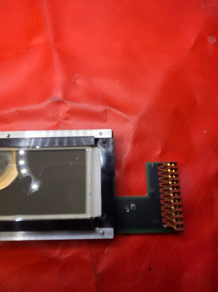
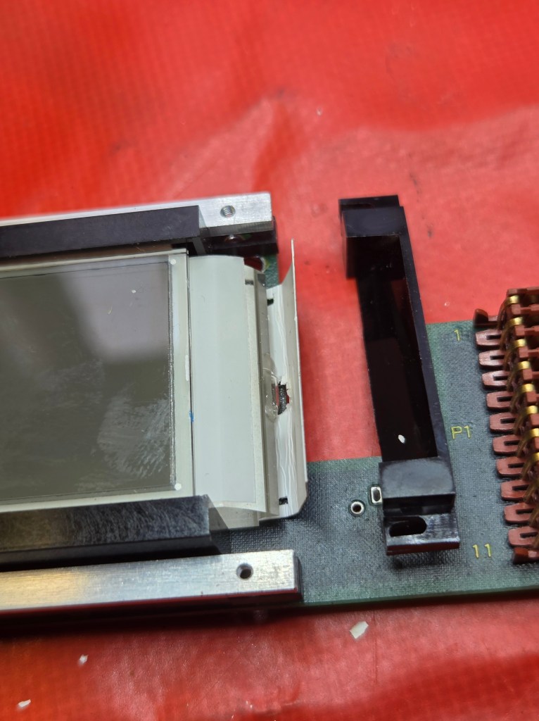
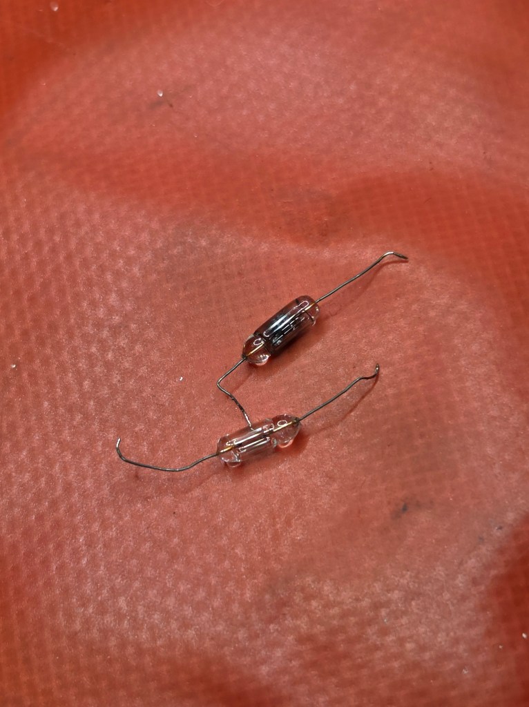
The globes can then be unsoldered – as expected they were open circuit. The plastic sheet securing them has some melting – clearly they got quite hot. Use solder wick to clear the connecting holes of solder.
Replacement
The globe supply is 5V at approx 110mA. I am not sure whether you can still get these globes but even if you could I wanted to replace them with a more reliable alternative so I never had to do this again!
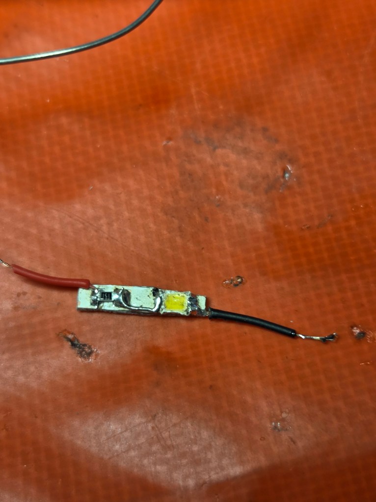
I had strips of bright white LEDS which were part of outside solar lights which I had bought at the local hardware to be enclosures for outside Meshtastic nodes. (BTW these are good for this, waterproof enclosure, Li-ion battery, charging panel and electronics). I cut off strips of 2 LEDS and trimmed the PC board they were on down to absolute minimum width to fit in the narrow space for the globe. I then unsoldered one LED and replaced it with a surface mount series resistor of suitable value. I had to solder a jumper between LED and resistor.
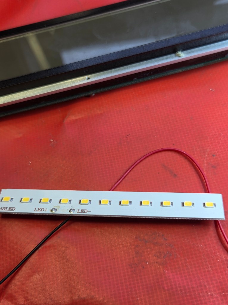
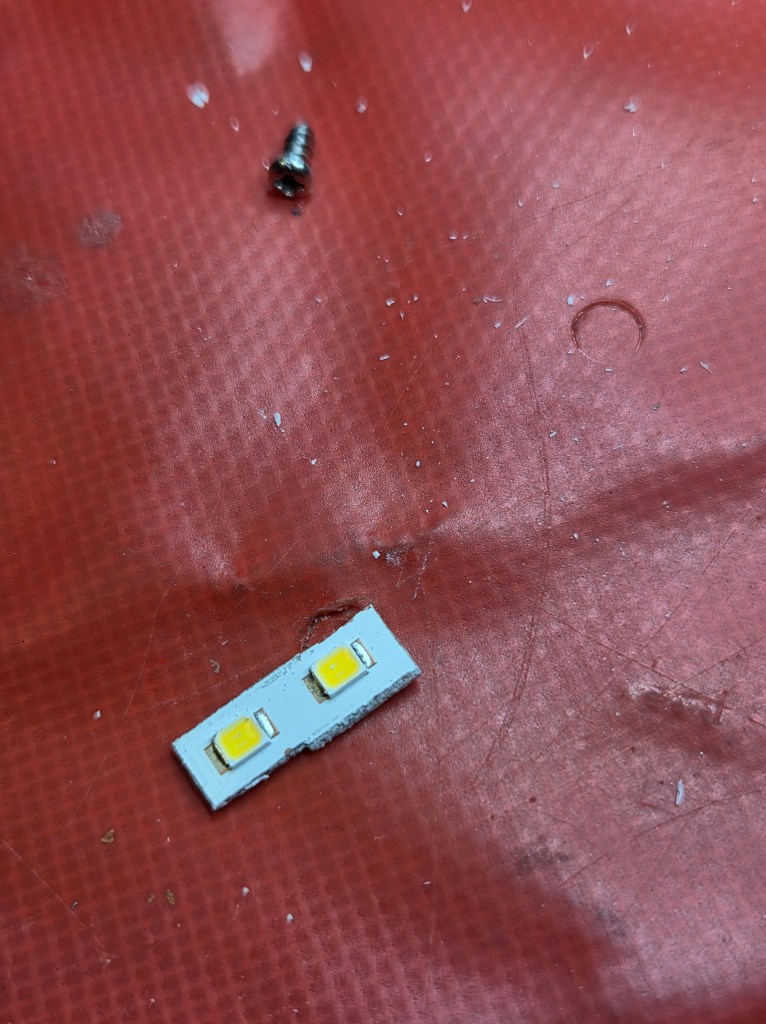
The LEDs have a prodigious light output at relatively low current. At 20mA they are blinding. Most standard LEDS run at 20-30mA. They conduct at about 2.7V. Thus the ideal would be about 120 ohms as a dropping resistor. This would give a current of
I = V/R
= (5-2.7)/120
= approx 19mA
I settled on 2X 220 ohm in parallel (as I didnt have 120 ohms) which would give approx 21mA on one side and 150 ohms which would give about 15mA on the other. The total dissipation is approx 100mW for diode and resistor which is well within their rating.
Polarity
The original globe did not require installation in a particular direction. But obviously the LEDS are polarized!
I tried navigating multiple poorly reproduced schematics on the net. In the end I found experimentally (I had to take it all apart and redo the connections!) that the positive side is COMMON on the schematic. Measure with an ohmmeter between the globe connections at both ends of the board – on one side they are connected together – this is the POSITIVE supply.
Solder your replacement light in place and reassemble. Hopefully you will be good to go!

I noted there was a slightly dim area in the backlight on the lower current side – not a problem in practice though. I wasnt inclined to redo the whole process!
Reference

